

 Product
 Brand
Brand Articles
 Tools
Tools
MSL and Floor Life: A Receiving-to-Reflow Checklist for ICs
Surface-mount reflow soldering exposes integrated circuits (ICs) to peak temperatures between 245°C and 260°C. When plastic-encapsulated microchips absorb moisture from ambient factory air, that trapped moisture flashes into high-pressure steam during rapid reflow heating. The resulting internal stress causes package delamination between the mold compound and die or lead frame, internal micro-cracking, bond-wire shearing, and explosive package rupture—a failure mode known across electronics manufacturing as the popcorn effect.
Over 90% of moisture-induced reflow defects produce zero visible external blisters or cracks. These internal fractures evade Automated Optical Inspection (AOI) and initial In-Circuit Testing (ICT), only to manifest as field failures under thermal and mechanical cycling.
Managing this risk requires a continuous chain of custody from the receiving dock to the reflow tunnel. This guide provides an operational, standard-compliant MSL floor life handling checklist governed by IPC/JEDEC J-STD-020 (component classification) and IPC/JEDEC J-STD-033[3] (packaging, shipping, dry storage, and handling).
Receiving-to-Reflow Decision Architecture
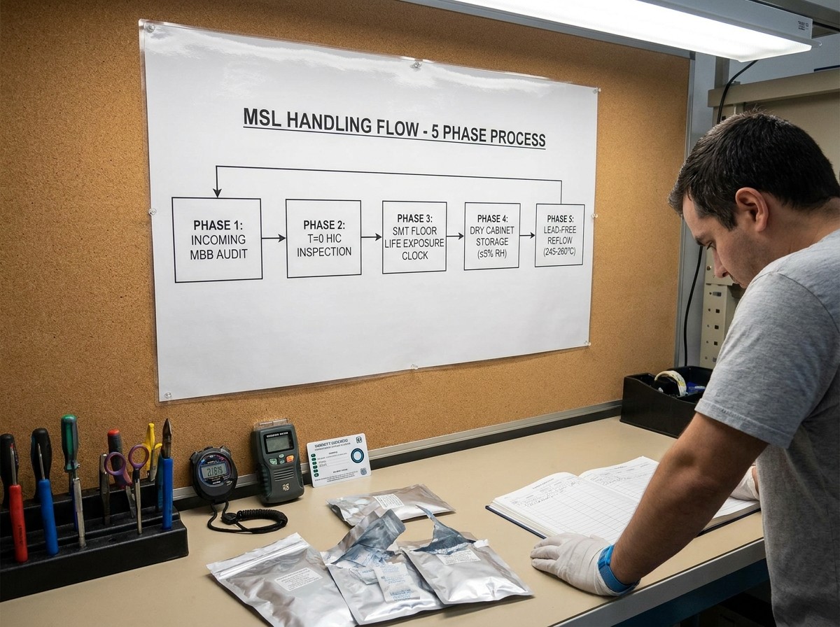
The following chronological decision flow governs moisture-sensitive surface-mount devices (SMDs) through the manufacturing facility:
Incoming Receiving Inspection
Check outer Moisture Barrier Bag (MBB) for tears, punctures, or vacuum loss.
Verify Caution Label: extract Moisture Sensitivity Level (MSL), Bag Seal Date, and package thickness.
If the bag is physically breached: quarantine immediately for baking evaluation.
If the bag is intact: store in climate-controlled warehouse racking at less than 40°C and 90% Relative Humidity (RH).
Unsealing at IQC or SMT Staging (TheGate)
Cut the MBB cleanly near the factory seal to preserve foil for potential resealing.
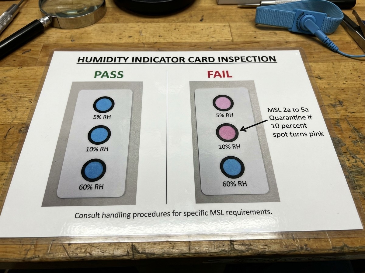
Read the enclosed 3-spot Humidity Indicator Card (HIC) within 1 to 2 minutes at 23 ± 5°C.
Pass: HIC indicates dry condition (10% spot is blue for MSL 2a–5a; 60% spot is blue for MSL 2). Affix a physical Floor Life Traveler, record the unsealing timestamp (), and begin cumulative tracking.
Fail: Critical spot indicates moisture exposure (10% spot is pink/discolored). Stop work immediately, quarantine the lot, and transfer to process engineering for baking qualification.
SMT Assembly Line Exposure
Load reels/trays onto feeder carts. The cumulative floor-life clock runs continuously.
Verify factory ambient conditions remain at or below 30°C and 60% RH.
Account for feeder dwell time across active production and changeover pauses.
Interrupted Production or Partial Run
Pause exposure clock: If production halts for more than 2 hours, transfer opened reels into an active dry cabinet maintained at or below 5% RH.
Resume production: Retrieve reels, record check-out time, subtract remaining floor-life budget, and return to feeders.
Disposition at Reflow or Expiration
Within Floor Life: Proceed to solder paste printing, high-speed placement, and reflow profile matching the package classification temperature ()[2].
Floor Life Expired: Do not run parts through the oven. Quarantine lot for baking based on carrier packaging thermal limits (low-temperature bake in tape or high-temperature bake in matrix trays).
Core Distinctions: MSL Rating, Bag Seal Date, Shelf Life, and Floor Life
SMT quality audits frequently expose confusion among warehouse material handlers and line operators regarding package timestamps. Treating a Bag Seal Date as a floor-life limit or assuming hermetically sealed bags last indefinitely leads directly to assembly line halts or latent component failures.
The Three Operational Clocks
Moisture Sensitivity Level (MSL): A structural classification assigned under IPC/JEDEC J-STD-020 ranging from Level 1 (immune) to Level 6 (critically sensitive). It defines the rate at which an unpackaged IC reaches critical moisture saturation when exposed to factory air.
Bag Seal Date: The calendar timestamp recorded on the caution label indicating when the component vendor sealed the MBB with active desiccant and an HIC.
Sealed Shelf Life: The maximum allowable duration an unopened, undamaged MBB can remain in warehouse storage while maintaining an internal micro-environment below 10% RH. Standard minimum shelf life is 12 months (and up to 36 months depending on manufacturer qualification) when stored at less than 40°C and 90% RH.
Floor Life: The maximum cumulative allowable time an unsealed component may remain in factory ambient air prior to reflow soldering. Standard floor life is defined strictly at factory reference conditions of 30°C or less and 60% RH.
Operational Parameter Comparison
| Parameter | Official Definition | Standard Reference Condition | Clock State / Operational Behavior | Governing Standard |
|---|---|---|---|---|
| MSL Rating | Package susceptibility rating to moisture-induced stress during solder reflow. | Classification soak per J-STD-020 Table 5-1. | Static parameter; dictates allowable floor-life hours and reflow peak profile (). | IPC/JEDEC J-STD-020 |
| Bag Seal Date | Date the manufacturer completed vacuum dry-packing with desiccant and HIC. | Packaged at factory ambient; sealed hermetically. | Static baseline timestamp printed on MBB exterior caution label. | IPC/JEDEC J-STD-033[1] |
| Sealed Shelf Life | Allowable storage period of an unopened, undamaged MBB before desiccant exhausts. | andstorage ambient. | Active countdown while sealed; paused indefinitely only when maintained in manufacturer dry pack. | IPC/JEDEC J-STD-033 |
| Floor Life | Maximum allowable cumulative open-air workshop exposure prior to reflow. | andfactory ambient. | Initiates atupon MBB unsealing; runs continuously unless paused indry storage. | IPC/JEDEC J-STD-033 |
If factory workshop conditions exceed the baseline of 30°C and 60% RH, allowable floor life decreases exponentially. For example, under higher ambient humidity, an MSL 3 component rated for 168 hours may see its safe assembly window compressed to under 48 hours, requiring formal derating calculations per J-STD-033 tables.
The Receiving-to-Reflow Checklist: A 5-Phase Operating Procedure
Follow this detailed 5-phase standard operating checklist across all manufacturing shifts:
Phase 1: Incoming Receiving and Warehouse Verification
Inspect MBB Physical Barrier Integrity
Inspect the exterior barrier pouch for tears, creases, punctures, micro-abrasions, or seal delamination.
Check for proper vacuum conformity. If the barrier bag fits loosely or shows ballooning, the hermetic seal has failed.
Action on breach: Do not admit compromised bags to general inventory. Move the reel to incoming quarantine for immediate engineering review.
Audit the JEDEC Caution Label
Verify the component Part Number (PN) matches the purchase order and manufacturer label.
Record the stated MSL level (1, 2, 2a, 3, 4, 5, 5a, or 6).
Check the Bag Seal Date. Calculate elapsed shelf life. If the date exceeds the manufacturer-guaranteed shelf life (typically 12 to 24 months), flag the material for internal evaluation or HIC inspection before issuing to production.
Check the peak package body temperature (or, typically 245°C or 260°C) to ensure downstream reflow oven profiles do not exceed component ratings.
Control Storage Ambient
Keep unopened bags in clean, climate-controlled warehouse racking. Maintain storage conditions below 40°C and 90% RH. Never store moisture-sensitive inventory outdoors or in non-conditioned staging areas.
Phase 2: Bag Opening and Immediate HIC Inspection (TheGate)
Moisture Sensitivity Level (MSL) - Surface Mount Process
Clean Opening Procedure
Use an anti-static clean scissor or cutting tool to open the top edge of the MBB just beneath the factory heat seal.
Do not tear or mangle the bag; preserve the pouch length to allow subsequent vacuum heat-resealing if the reel is only partially consumed.
Inspect the Humidity Indicator Card (HIC) Immediately
For MSL 2 Devices: Check the 60% RH spot. If the 60% spot is blue, the dry pack is verified. If the 60% spot is pink or discolored, the internal bag atmosphere exceeded safe storage limits.
For MSL 2a through MSL 5a Devices: Check the 5% and 10% spots. If the 10% spot is blue, proceed. If the 10% spot is pink/discolored and the 5% spot is pink, moisture has penetrated the barrier. The desiccant is spent and the components have absorbed ambient water.
Remove the HIC and inspect it within 1 to 2 minutes of exposure to factory air. Ambient moisture will rapidly alter the indicator chemistry if inspection is delayed.
Read the card at standard room ambient ().
Inspect the color response across the spots (typically 5%, 10%, and 60% RH):
Execute Gatekeeping Action
HIC Passed: Discard spent desiccant (or keep within bag if immediate resealing is planned). Affix the physical Floor Life Traveler to the reel flange. Mark the current date and time as.
HIC Failed: Do not mount components onto pick-and-place lines. Immediately tag the reel as REJECTED / QUARANTINE, segregate the lot, and route to process engineering for baking disposition per IPC/JEDEC J-STD-033.
Phase 3: SMT Workshop Floor-Life Management and Cumulative Exposure
Once the MBB is unsealed, the exposure clock begins. SMT production must track ambient exposure across all handling stages.
Standard Floor-Life Specifications (IPC/JEDEC J-STD-033 Table 5-1)
| Level | Floor Life (Out of Bag) at Factory Baseline Condition | Environmental Baseline |
|---|---|---|
| MSL 1 | Unlimited | |
| MSL 2 | 1 Year | |
| MSL 2a | 4 Weeks (28 days) | |
| MSL 3 | 168 Hours (7 days)[4] | |
| MSL 4 | 72 Hours (3 days) | |
| MSL 5 | 48 Hours (2 days) | |
| MSL 5a | 24 Hours (1 day) | |
| MSL 6 | Mandatory Bake Before Use; reflow within window stated on label |
Cumulative Exposure Accounting
Exposure is strictly additive. An IC exposed across multiple production shifts, kitting setups, or prototype builds accumulates exposure according to:
If an MSL 3 IC (168-hour limit) is exposed to ambient air for 30 hours during Line Run 1, safely paused in a dry cabinet for 4 days, and brought back out for Line Run 2, the starting consumed floor life is 30 hours. The remaining allowable exposure is.
SMT Feeder Dwell Time
Components mounted on pick-and-place tape feeders, matrix tray changers, or feeder carts are actively absorbing moisture.
Floor-life logging must continue while components sit on the machine.
If a production line stops for shift handovers, line balancing, or maintenance exceeding 2 hours, strip moisture-sensitive reels from feeder banks and store them in ultra-low humidity dry cabinets.
Thin fine-pitch packages (such as QFPs, TQFPs) and Ball Grid Arrays (BGAs) have thin mold compound barriers over the silicon paddle. These packages saturate rapidly, leaving very little tolerance for untracked feeder dwell.
Phase 4: Interrupted Production: Resealing vs. Dry Storage Cabinets
When production runs conclude with partial reels remaining, operators must immediately protect components from further moisture uptake.
Pausing the Clock via Ultra-Low Humidity Cabinets ()
Storing unsealed SMDs in an active desiccant dry cabinet maintaining at or below 5% RH stops the floor-life clock.
Under IPC/JEDEC J-STD-033, storage atis equivalent to storage inside a pristine, unopened MBB. It preserves remaining floor-life hours without penalty.
TheCabinet Threshold (Limited Pause)
Storage in cabinets holding between 5% and 10% RH does not pause the clock indefinitely.
For MSL 2 through MSL 3 parts, storage up to 10% RH pauses the clock only if the cumulative ambient exposure prior to storage was less than 12 hours. For longer prior exposures, storage at 10% RH permits only limited floor-life extensions defined in J-STD-033 Table 4-2.
Cabinet Door-Opening Recovery Time
Production dry cabinets must feature rapid recovery systems. Ensure the cabinet recovers to within 15 minutes after door access per practical MSD storage guidelines[5]. Frequent door openings that keep internal relative humidity above 10% invalidate clock pauses and risk uncontrolled moisture absorption.
Short-Term Floor-Life Resetting Without Baking (J-STD-033 Table 4-3)
MSL 2, 2a, or 3: If exposed for no more than 12 hours at, soaking in adry cabinet for 5 times the exposure time resets floor life to zero.
MSL 4, 5, or 5a: If exposed for no more than 8 hours at, soaking in adry cabinet for 10 times the exposure time resets floor life to zero.
Example: An MSL 3 reel exposed on a feeder for 6 hours can be fully reset to 168 hours of floor life by holding it in a certifieddry cabinet for 30 consecutive hours ().
Components exposed for brief periods can have their consumed floor life reset to zero without thermal baking by soaking in a
dry cabinet:
Temporary MBB Resealing with Fresh Desiccant
If dry cabinet space is unavailable or components are being shipped to another facility, parts may be heat-resealed inside a clean MBB.
Operators must discard old desiccant and insert fresh, active desiccant calculated to MIL-D-3464 standards based on bag surface area. Insert a fresh 3-spot HIC. Evacuate excess air and hermetically seal the open edge using an industrial heat sealer.
Phase 5: Exceeded Floor Life: Baking Protocol and Carrier Thermal Limits
If cumulative exposure exceeds rated floor life, or if an HIC shows internal bag failure upon initial unsealing, components must undergo dry baking before reflow.
Dispelling the Universal 125°C Baking Myth
Setting an oven to 125°C for 24 hours without reviewing packaging specs is a dangerous shop-floor error. Baking temperatures and soak times are governed by package body thickness, MSL rating, and—most critically—the thermal limitations of the packaging carrier.
Packaging Carrier Thermal Boundaries
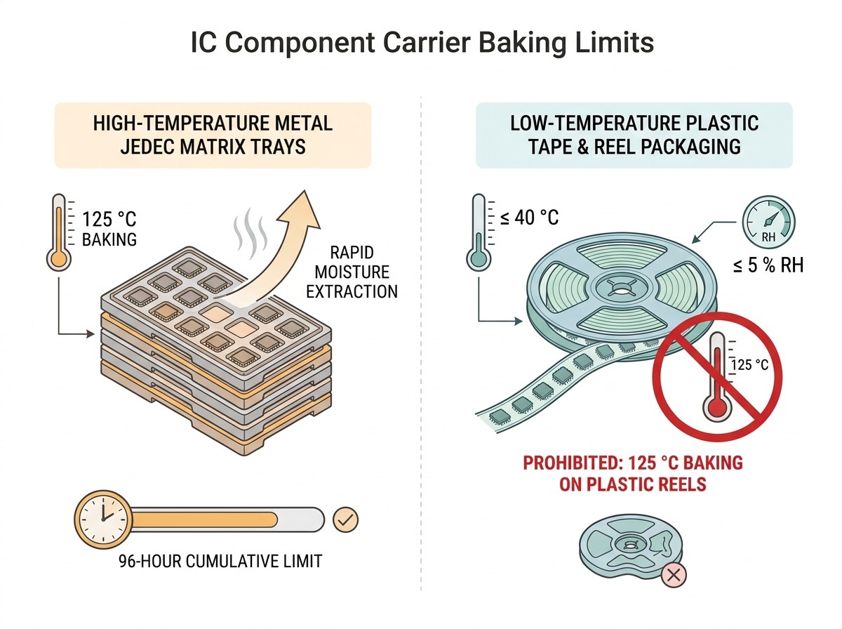
Standard Tape and Reel Packaging: Standard carrier tapes (embossed polystyrene or polycarbonate), cover tapes, and plastic reels soften, distort, or melt at temperatures between 45°C and 60°C. Baking an intact reel at 125°C destroys the carrier, welds the cover tape to the pocket margins, and ruins pick-and-place feeder indexing.
Low-Temperature In-Tape Baking: When components cannot be de-reeled, bake within the original packaging using low-temperature cycles (typically 40°C to 45°C at). Because low temperatures drive moisture out slowly, these bakes require prolonged cycles—often several days to several weeks—depending on package thickness and MSL.
High-Temperature Tray Baking (125°C): High-temperature bakes (typically 125°C) require de-reeling components and transferring them into certified high-temperature matrix trays or metal fixtures rated for. This extracts moisture rapidly (often between 8 and 48 hours depending on package thickness).
Solderability and Intermetallic Limits
Baking is not an unlimited reset mechanism:
The 96-Hour Rule: Per IPC/JEDEC J-STD-033 Section 4.2.7.1[6], cumulative baking time at temperatures between 90°C and 125°C must not exceed 96 hours.
Excessive thermal baking accelerates intermetallic growth at lead interfaces, oxidizes lead plating finishes (tin, gold, or silver alloys), and degrades solderability, causing non-wetting or micro-voiding during reflow.
If a component lot requires repeated baking that exceeds 96 cumulative hours at high temperature, submit sample devices to solderability testing per J-STD-002 before mounting on production assemblies.
Beyond Vendor Myths: Addressing Risky MSL Handling Practices
Myth 1: "Dropping fresh desiccant into an open bag resets the component floor life to zero."
Scientific Reality: Desiccant scavenges airborne water molecules inside an enclosed volume; it does not extract moisture that has already diffused into an IC's epoxy matrix. Re-bagging with fresh desiccant only pauses further absorption or slows uptake; it does not erase accumulated floor-life hours. Only qualified thermal baking or an extended dry-cabinet soak (per Table 4-3 rules) restores floor life.Myth 2: "Placing open components in a dry cabinet instantly resets their clock."
Scientific Reality: Ultra-low humidity dry cabinets () halt or pause the countdown. Unless the component had a very short ambient exposure that was subsequently offset by an extended soak (e.g., 5× or 10× exposure duration per standard rules), placing parts in a dry cabinet freezes accumulated exposure time—it does not zero it out.Myth 3: "If parts exit the reflow oven without visible blisters, the moisture level was acceptable."
Scientific Reality: Catastrophic visual swelling and external cracking represent only a tiny fraction of moisture reflow failures. Internal delamination between the die paddle and mold compound, micro-cracking across silicon passivation, and lifted ball bonds remain completely hidden within the epoxy. Verifying these defects requires Scanning Acoustic Microscopy (C-SAM) or destructive physical cross-sectioning.Myth 4: "All IC packages can be baked on their original reels at 125°C."
Scientific Reality: Plastic packaging carriers cannot withstand 125°C. Baking reels at 125°C will warp the carrier tape and melt reel flanges, causing feeder jams on SMT pick-and-place lines. Always verify whether the packaging is marked as high-temperature or transfer parts to metal matrix trays.
Printable Shop-Floor Traveler: MBB Unsealing and Floor-Life Tracking Log
Manual and semi-automated production environments require a physical traveler attached directly to every unsealed reel flange, tray stack, or moisture barrier bag. The standardized template below provides end-to-end custody traceability across shifts, kitting operations, and dry storage pauses—ready to be printed or transferred directly to physical shop-floor travelers.
Component Traceability Header
| Field | Record / Value |
|---|---|
| Component Part Number: | __________________________________________________ |
| Reel / Lot Identification ID: | __________________________________________________ |
| Component Manufacturer: | __________________________________________________ |
| Package Body Thickness: | ________________ mm |
| MSL Classification: | [ ] 2 [ ] 2a [ ] 3 [ ] 4 [ ] 5 [ ] 5a [ ] 6 |
| Total Allowable Floor Life: | ____________ Hours (at) |
| MBB Seal Date (from label): | _____ / _____ / 20___ |
| Initial Unsealing Date & Time: | _____ / _____ / 20___ at ____:____ |
| Initial HIC Inspection (23±5°C): | 5% Spot: [ ] Blue [ ] Pink | 10% Spot: [ ] Blue [ ] Pink |
| Gatekeeping Verification: | [ ] PASS (Proceed) | [ ] FAIL (Quarantine for Disposition) |
Cumulative Floor-Life and Dry Storage Ledger
| Event No. | Out of Storage / Line Open (Date & Time) | In to Dry Storage / Oven (Date & Time) | Elapsed Ambient Exposure (Hours) | Cumulative Consumed Hours | Remaining Floor Life (Hours) | Storage Unit ID & RH % | Operator Signature |
|---|---|---|---|---|---|---|---|
| 01 | ___/___/___ __:__ | ___/___/___ __:__ | ______ Hrs | ______ Hrs | ______ Hrs | Cab: _____ (____%) | [ ] |
| 02 | ___/___/___ __:__ | ___/___/___ __:__ | ______ Hrs | ______ Hrs | ______ Hrs | Cab: _____ (____%) | [ ] |
| 03 | ___/___/___ __:__ | ___/___/___ __:__ | ______ Hrs | ______ Hrs | ______ Hrs | Cab: _____ (____%) | [ ] |
| 04 | ___/___/___ __:__ | ___/___/___ __:__ | ______ Hrs | ______ Hrs | ______ Hrs | Cab: _____ (____%) | [ ] |
| 05 | ___/___/___ __:__ | ___/___/___ __:__ | ______ Hrs | ______ Hrs | ______ Hrs | Cab: _____ (____%) | [ ] |
| 06 | ___/___/___ __:__ | ___/___/___ __:__ | ______ Hrs | ______ Hrs | ______ Hrs | Cab: _____ (____%) | [ ] |
Disposition at Expiration or Line Completion
Reflow Completed Within Safe Window: Total Exposure Hours: ______ | Lead SMT Inspector Signature: _________________________
Floor Life Exceeded (Quarantined for Bake): Bake Temperature: ______°C | Required Soak Time: ______ Hours
Carrier Verification: [ ] De-reeled to High-Temp Metal Trays (125°C) | [ ] In-Tape Low-Temp Bake (40°C,)
Process Engineer Release: Signature: _________________________________ | Date: _____ / _____ / 20___
Shop-Floor MSL Violations, Ambient Derating, and Troubleshooting
Violation 1: Unmonitored Feeder Carts Left on the Line During Weekend Shutdowns
Symptom: On Friday evening, an SMT line finishes a production run. Partially consumed MSL 3 reels remain mounted on pick-and-place feeder carts in ambient shop-floor air until Monday morning, accumulating 62 hours of unlogged exposure.
Root Cause: Failure to execute line shutdown checklist requiring sensitive material transfer to dry cabinets during stoppages exceeding 2 hours.
Engineering Action: Audit the floor-life traveler. Add the 62 unmonitored hours to prior cumulative exposure. If total consumed hours are below 168 hours, calculate remaining budget and log immediately. If total exposure exceeds 168 hours, strip reels from feeders, issue a non-conformance quarantine report, and transfer to process engineering for baking.
Violation 2: Summer HVAC Excursions (Ambient Temperature and Humidity Spikes)
Symptom: Facility HVAC cooling or dehumidification fails, driving SMT cleanroom conditions to 32°C and 75% RH.
Root Cause: Environmental drift above the baseline reference condition of 30°C and 60% RH.
Engineering Action: Apply J-STD-033 environmental derating tables immediately. When relative humidity reaches 70–80%, moisture diffusion into plastic packages accelerates rapidly. For MSL 3 packages, allowable exposure drops from 168 hours to under 48 hours. Freeze active lines, recalculate remaining margins for all mounted reels, and transfer inventory intodry storage until room climate controls stabilize.
Violation 3: Unrecorded Reel Splitting and Kitting
Symptom: A warehouse technician splits a 5,000-piece mother reel into five 1,000-piece mini-reels for separate production lines without copying the open timestamp.
Root Cause: Splitting packaging without generating sub-lot traveler documentation.
Engineering Action: Require mandatory generation of daughter travelers whenever reels are divided. Each daughter reel must inherit the exact cumulative exposure hours consumed by the mother reel at the moment of splitting. If historical exposure cannot be verified, quarantine all child reels for baking.
Violation 4: Pick-and-Place Feeder Jams After High-Temperature Reel Baking
Symptom: Pick-and-place optical sensors report feeder pick errors; carrier tape pocket pitch is distorted, and the cover tape is melted to the pocket edges.
Root Cause: Operators placed plastic reels into a 125°C baking oven instead of de-reeling into metal matrix trays or running a 40°C low-temperature bake.
Engineering Action: Scrap damaged carrier tape and packaging. Inspect component leads for thermal deformation and finish degradation. Re-tape surviving parts into fresh ESD-safe carrier tape or load into matrix trays. Update operator Standard Operating Procedures (SOPs) with strict packaging carrier thermal rules.
Frequently Asked Questions
What does Moisture Sensitivity Level 3 (MSL 3) mean in practice for an SMT line?
MSL 3 specifies that once the hermetically sealed Moisture Barrier Bag is opened, the integrated circuit has a maximum allowable floor life of 168 hours (exactly 7 days) in a factory ambient environment maintained at or below 30°C and 60% RH. All placement and solder reflow processes must finish within this 168-hour window. If factory humidity or temperature exceeds these limits, floor life must be derated per IPC/JEDEC J-STD-033 tables.
Does placing exposed ICs into a dry storage cabinet reset their floor life to zero?
No. Storing exposed components in an ultra-low humidity dry cabinet () pauses the floor-life countdown, preserving whatever time budget remains. Fully resetting the clock to zero requires either a qualified thermal bake cycle or an extended dry-soak period specified in J-STD-033 Table 4-3 (for instance, soaking parts for 5 times the exposed duration for MSL 2–3 devices exposed for less than 12 hours).
Can I bake moisture-sensitive components directly in their plastic tape and reel packaging?
Only during a low-temperature bake (typically 40°C to 45°C with) over an extended period. Standard plastic carrier tapes, cover tapes, and reels cannot tolerate standard high-temperature baking at 125°C; they soften, warp, and melt at temperatures above 45°C to 60°C. To bake components at 125°C, operators must de-reel parts and transfer them into high-temperature metal or matrix trays rated for high heat.
What immediate protocol should be followed if the Humidity Indicator Card is pink upon opening?
If the critical indicator spot (the 10% spot for MSL 2a–5a components, or the 60% spot for MSL 2 devices) has turned pink or lavender when read at 23 ± 5°C, the protective micro-environment has failed. Stop work immediately. Do not release the parts to the assembly floor. Quarantine the lot, flag it with a non-conformance tag, and route the material to an SMT process engineer to determine the appropriate bake schedule based on package body thickness and MSL rating.
What is the specific handling requirement for MSL 6 devices?
MSL 6 devices have a floor life of zero. They cannot be mounted straight out of the bag under any circumstances. MSL 6 components must undergo a mandatory bake according to the manufacturer's caution label prior to assembly, and they must undergo reflow soldering strictly within the post-bake window specified on the packaging.
Sources and references used for this guide
JOINT INDUSTRY STANDARD: Handling, Packing, Shipping and Use of Moisture/Reflow Sensitive Surface Mount Devices (J-STD-033)
Source type: standards body
Used for: Primary standard text for MSL floor-life exposure tables, HIC reading thresholds (10% spot), dry cabinet storage (<5% RH pause rules), and low/high temp baking cycles.
Caution: Authoritative standard text hosted on NAVSEA repository; verify plant procedures align with latest published J-STD-033 revision.MSL Ratings and Reflow Profiles (Rev. A)
Source type: official company documentation
Used for: Authoritative semiconductor manufacturer analysis of package moisture absorption, popcorn delamination mechanics during reflow, and temperature/RH derating tables.
Caution: Manufacturer technical application report; specific reflow profile curves must match individual component part numbers.JEDEC J-STD-033 Standard Portal
Source type: standards body
Used for: Establishing official standard lineage, governing scope, and boundary between J-STD-020 classification and J-STD-033 factory handling.
Caution: Standards committee landing page; formal full standards require organizational access.Murata MSL3 Product Handling Manual
Source type: official company documentation
Used for: Real-world tier-1 component manufacturer SOP for MSL 3 unsealing, MBB handling, 168-hour floor life logging, and factory environmental conditions.
Caution: Component application note; specific to Murata product series but adheres to J-STD-033 baseline.IPC/JEDEC J-STD-033: A Practical Guide to Moisture Sensitive Device Storage
Source type: vendor article
Used for: Operational metrics for industrial dry cabinets, <5% RH indefinite pause mechanics, and cabinet door recovery time benchmarks (<15 minutes).
Caution: Industrial equipment vendor source; use for practical dry cabinet operational parameters, not as sole legal standard authority.IPC/JEDEC J-STD-033B.1 Standard Extract
Source type: reputable professional source
Used for: Standard floor life classification table (MSL 1 to MSL 6) and historical reference conditions (30°C / 60% RH).
Caution: Technical repository reprint; cross-checked against current standard specifications.
 UTMEL
UTMEL
We are the professional distributor of electronic components, providing a large variety of products to save you a lot of time, effort, and cost with our efficient self-customized service. careful order preparation fast delivery service
 Discovering New and Advanced Methodology for Determining the Dynamic Characterization of Wide Bandgap DevicesSaumitra Jagdale15 March 20242833
For a long era, silicon has stood out as the primary material for fabricating electronic devices due to its affordability, moderate efficiency, and performance capabilities. Despite its widespread use, silicon faces several limitations that render it unsuitable for applications involving high power and elevated temperatures. As technological advancements continue and the industry demands enhanced efficiency from devices, these limitations become increasingly vivid. In the quest for electronic devices that are more potent, efficient, and compact, wide bandgap materials are emerging as a dominant player. Their superiority over silicon in crucial aspects such as efficiency, higher junction temperatures, power density, thinner drift regions, and faster switching speeds positions them as the preferred materials for the future of power electronics.
Read More Applications of FPGAs in Artificial Intelligence: A Comprehensive GuideUTMEL29 August 20255467
This comprehensive guide explores FPGAs as powerful AI accelerators that offer distinct advantages over traditional GPUs and CPUs. FPGAs provide reconfigurable hardware that can be customized for specific AI workloads, delivering superior energy efficiency, ultra-low latency, and deterministic performance—particularly valuable for edge AI applications. While GPUs excel at parallel processing for training, FPGAs shine in inference tasks through their adaptability and power optimization. The document covers practical implementation challenges, including development complexity and resource constraints, while highlighting solutions like High-Level Synthesis tools and vendor-specific AI development suites from Intel and AMD/Xilinx. Real-world applications span telecommunications, healthcare, autonomous vehicles, and financial services, demonstrating FPGAs' versatility in mission-critical systems requiring real-time processing and minimal power consumption.
Read More The 2026 Engineer’s Guide: Choosing the Right MCU for Your Next IoT & New Energy ProjectUTMEL30 April 20261615
A comprehensive comparison of 2026's leading MCUs from ST, NXP, and Microchip across power efficiency, processing performance, connectivity, and ecosystems to help engineers select the optimal chip for next-gen IoT and new energy projects.
Read More AI Server Components: Engineering Next-Gen Data Center Hardware for 100kW RacksUTMEL15 May 2026887
The transition from traditional enterprise IT to AI-driven workloads has rendered legacy data center hardware obsolete, forcing infrastructure planners to re-engineer server components for extreme thermal environments.
Read More The Practical Engineer’s Guide to the NE555N Timer: Pinout, Setup, and TroubleshootingUTMEL29 May 2026669
This comprehensive guide explores the NE555N timer, detailing its 8-pin layout, internal architecture, and key datasheet specifications. It compares the bipolar IC to CMOS variants and details setup configurations for astable, monostable, and bistable modes. Additionally, the guide offers practical troubleshooting advice to prevent common breadboard failures, such as floating reset pins and electrical noise issues.
Read More
Subscribe to Utmel !
![HCS365/P]() HCS365/P
HCS365/PMicrochip Technology
![UCC20520DWR]() UCC20520DWR
UCC20520DWRTexas Instruments
![HCS200/P]() HCS200/P
HCS200/PMicrochip Technology
![DLPA2005ERSLR]() DLPA2005ERSLR
DLPA2005ERSLRTexas Instruments
![ATSHA204-SH-CZ-T]() ATSHA204-SH-CZ-T
ATSHA204-SH-CZ-TMicrochip Technology
![SN74AVC6T622PWR]() SN74AVC6T622PWR
SN74AVC6T622PWRTexas Instruments
![UCC5350MCD]() UCC5350MCD
UCC5350MCDTexas Instruments
![FOD3184S]() FOD3184S
FOD3184SON Semiconductor
![FOD8314T]() FOD8314T
FOD8314TON Semiconductor
![ACPL-W343-000E]() ACPL-W343-000E
ACPL-W343-000EBroadcom Limited


